|
Main Menu
|
|
|
|
My 2007 4Runner
|
|
|
|
|
|
|
|
|
|
|
|
|
*New*
|
|
|
|
|
|
|
|
|
|
|
|
|
|
|
|
|
|
|
|
*New*
|
|
*New*
|
|
|
|
|
|
|
|
|
|
|
|
|
|
|
|
|
|
|
|
|
|
|
|
|
|
|
|
|
|
*New*
|
|
|
|
|
|
|
|
|
|
|
|
|
|
|
|
|
|
|
|
|
|
|
|
|
|
|
|
|
|
|
|
|
|
|
*New*
|
|
*New*
|
|
*New*
|
|
|
|
|
|
|
|
*New*
|
|
*New*
|
|
*New*
|
|
*New*
|
|
|
4Runner History
|
|
|
|
Other
|
|
|
|
|
Concept:
This modification adds much needed front and rear footwell lighting on a 4th generation 2007 Toyota 4Runner.
Led (light emitting diode) type lighting will be used. These lights will be wired to automatically turn on when any door is
unlocked using a key or keyless transmitter, or if any door is opened.
The standard feature that shuts off the factory dome lighting system after 30 minutes of being inadvertently left on will be used in
conjunction with this mod to prevent excess battery drain. The footwells will fade in and out just as the factory dome lights do.
Additionally a three position switch will be added so that this mod can be set to automatic mode, turned on "on demand", or be switched off.
The off position of the switch will come in handy when working on the vehicle for long periods of time while repeatedly opening and closing the door,
which will reset the 30 minute automatic dome relay power off feature. The on position will come in handy at night to turn on only the footwell
lighting while the vehicle is in motion.
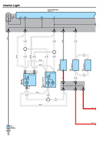
What needs to be accomplished:
For the footwell lights to come on automatically when opening the doors, this mod requires that the Body Electronic Control Unit's (ECU)
Interior Light Enable (ILE) circuit be brought to the negative side of the footwell lights. For the footwell lights to shut off automatically
after being left on for more than 30 minutes with the vehicle off, requires the positive side of the footwell lights to be powered from the
factory dome relay circuit.
First we will disassemble some interior trim pieces to gain access to areas in which we will run wiring.
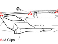
Remove driver side lower finish panel for access to driver side interior relay/junction box.
Start out by disassembling the lower dash area as we need access to the driver side interior relay/junction box. To access this area,
first remove the two 10mm bolts holding the lower finish panel on. Pull the panel straight out to disengage 4 plastic clips still holding it on.
The trim ring around the key hole will just pop out on it's own as you are doing this. Remove the wire harnesses attached to each of the switches
located on the back side of this panel. Also on the back right side of this lower finish panel is the room temperature sensor harness (cooler thermistor),
detach this from the panel as well. You may leave the fuel door release and the hood release handles attached to the panel. The panel can be lowered
to the floor now.
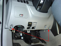
Remove driver side
lower finish panel |
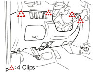
Pull to release 4 clips |
Remove lower bracket:
Remove two 10mm bolts holding the metal bracket around the bottom of the steering column. Disengage the 2 claws and remove the instrument panel lower
left hand bracket. Set bracket aside.
Remove instrument panel
lower bracket |
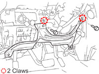
Disengage 2 claws |
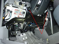
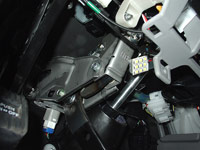
Lower down the driver side interior relay/junction box:
Remove wire clip and wire connector under steering column.
Remove three bolts holding driver side interior relay/junction box in place.
Remove bolt & bracket.
Pull down driver side interior relay/junction box to access back side.
Remove wire clip
and wire connector under steering column |
Remove three bolts |
Remove bolt & bracket |
Remove instrument cluster finish panel.
Pull firmly straight out to release seven clips.
Remove Rheostat (dash light dimmer) by unclipping wire harness on the back, depressing two tabs on this switch (top and bottom) and pulling the switch
out the front of this panel. Set panel aside.
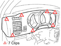
Remove instrument cluster
finish panel
Pull to release 7 clips |
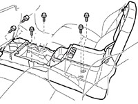
Center Console Removal.
To remove the center console, start by removing the shifter cover. It is held on with five clips and two claws. To remove you simply pull straight
up and back towards the rear of the vehicle. Before you can set the shift cover aside you need to remove any wire harnesses attached to it.
In my case I had to remove the DAC switch wiring and the 12v power point wiring. You may have more if you have the seat heaters,
rear air suspension or cigarette lighter options.
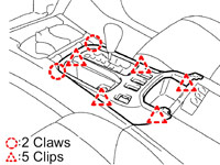
To remove shift cover
Pull to release 5 clips |
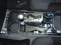
Next the console cover gets removed, this time there are 6 clips and two claws. To remove, again, pull straight up and back towards the rear of the
vehicle.
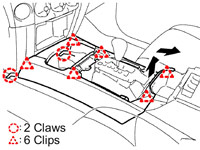
To remove console cover
Pull to release 6 clips |
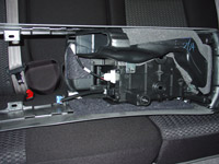
Before you can lift out the center console itself, you need to remove the upper panel side garnish. To remove, unclip the side covers just in front of
and below the cupholders. Then slide rearward to remove.
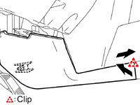
To remove side garnish
Pull to release 1 clip |
Then using a 10mm socket, remove the six bolts holding the console in place.
Remove six 10mm bolts |
Bolts removed |
Disconnect 4 more harnesses (automatic transmission shift lever illumination, accessory input for stereo, 115v power point and cup holder illumination),
then lift out entire console and set aside.
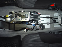
Lift out center console |
Set console aside |
Remove passenger side lower finish panel for access to passenger side underdash area.
Using a phillips screwdriver, remove one screw. Disengage three clips, and remove the No. 2 instrument panel under cover sub-assembly.
Remove Screw |
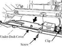
Disengage 3 clips |
Lower panel to floor |
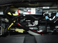
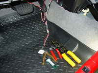
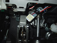
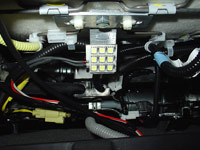
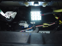
Tap into the factory Interior Light Enable (ILE) 12V- circuit.
I am going to tap into the ILE circuit on the back of the driver side interior relay/junction box, instrument panel wire harness
connector 1K, Pin #9, red with green stripe wire.
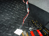
I tapped into the ILE wire using a Red 3M Scotchlok 558 Electrical IDC (insulation displacement connection) connector which is perfect for
22-16 AWG solid or stranded wire. The ILE wire appears to be, in my estimation, 20awg. Run your wire from here up to where you will mount
the dash switch. This will serve as your 12V negative wire for the led lights.
Connector 1K
Pin #9
Red with green stripe wire |
Scotchlok tap into ILE 12V- |
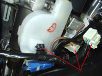
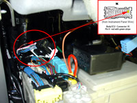
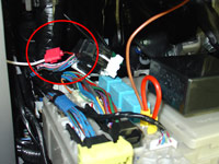
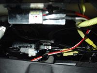
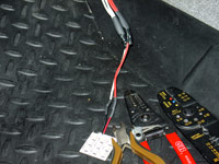
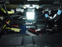
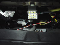
Tap into the factory dome relay 12V+ circuit.
I am going to tap into the Dome Relay circuit to obtain 12V+ power on the back of the driver side interior relay/junction box, instrument panel
wire harness connector 1J, Pin #22, solid red wire.
I tapped into the Dome Relay wire using a Red 3M Scotchlok 558 Electrical IDC (insulation displacement connection) connector which is perfect for
22-16 AWG solid or stranded wire. The Dome Relay wire appears to be, in my estimation, 20awg. Run your wire from here directly to the area
where we will locate the first of the four footwell lights. This would be the driver side footwell area. This wire will serve as your 12V
positive wire for the led underdash and underseat footwell lighting.
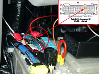
Scotchlok tap into Dome Relay 12V+
Connector 1J Pin #22
Solid red wire |
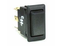
Switch information and installation.
As mentioned earlier, a switch will be added so that this mod can be set to either of three modes. 1) DOOR (Automatic) Mode, 2) OFF, 3) ON.
While a SPDT (single pole double throw) 12V on-off-on switch will accomplish this, I chose to go with a DPDT (double pole double throw) switch.
It is not necessary to buy this type of switch, and furthermore it will be wired up initially to use only one of the two poles.
The benefit of going with a dual pole dual throw type switch is that in the future, when I need to free up a factory switch blank on the
dash for another mod, I can remove my Maplight mod SPDT switch and relocate the wires on it to the unused pole on my DPDT
footwell mod switch thereby efficiently using only one switch for both mods.
Cole Hersee Part# 58027-07
Switch Type: Rocker Switch
Circuitry: Double Pole Double Throw (DPDT)
Terminals: 6 standard male brass blades, 0.25" wide x 0.50" long (6.35mm x 12.70mm).
Up Position: On (2-1 ; 5-4).
Center Position: Off.
Down Position: On (2-3 ; 5-6).
Electrical Rating: 25 amps at 12V DC.
Sealing: Weather resistant, gasket seal in housing.
Contacts: silver.
Illuminated: No.
Housing: Black plastic bezel and actuator.
Mounting Panel snap-in.
Panel Thickness: fits panels 0.093" to .187" (2.37mm x 4.76mm) thick.
Mounting Hole Dim. Inch 1.45" x .830" (36.83mm x 21.08mm).
Bezel Size: 0.964" x 1.69" (24.52mm x 43.16mm).
Actuator: inches 1.19" x .660" (30.3mm x 16.9mm).
Cole Hersee DPDT 58027-07 |
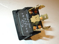
Cole Hersee DPDT 58027-07 |
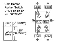
DPDT Switch Schematic |
Switch Labeling.
The Cole Hersee 58027-07 switch that I chose to use has a blank front which is perfect for a custom labeling job.
I purchased a set of Woodland Scenics Dry Transfer Decals MG721 White Gothic Letters. To protect it I went with Testors Dullcote 3oz Spray Can TES1260.
To layout the lettering as straight and centered as possible, I used some leftover 25 year old pinstriping I had laying around from my 1984 Oldsmobile Cutlass Calais project.
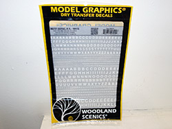
Woodland Scenics
Dry Transfer Decals
MG721 White Gothic Letters |
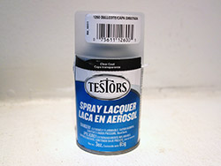
Testors Dullcote
3oz Spray Can
TES1260 |
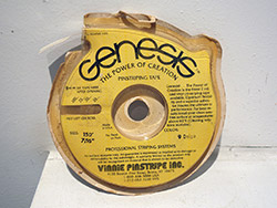
Pinstriping |
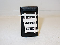
Laying out the
Dry Transfer Labeling |
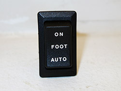
Lettering completed |
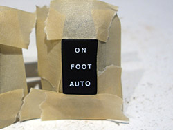
Spraying
the matte finish
protective topcoat |
Switch installed |
Switch mounting.
The Cole Hersee 58027-07 switch that I chose to use fits perfectly in the instrument cluster finish panel (upper dash) cutouts with
no modification or trimming necessary to either the switch or the panel. Though the switch does not snap lock into place due to the
thickness of the panel, the fit on the sides is more than tight enough to hold it in place.
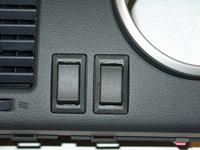
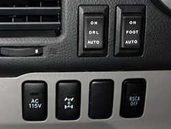
Switches mounted in dash |
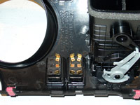
A look from the back |
Switch wiring.
At this point we have already ran one wire to the switch location. This wire was from the ILE circuit.
I crimped onto the end of this wire, a 3M Nylon Fully Insulated Female Disconnect with insulation grip interlock barrel.
These disconnects fit quite tightly onto the switch prongs which is why I prefer the type that have a insulation grip interlock barrel.
These type of connectors require a double crimping method, the first to secure the copper wire, the second on the wires insulation
which further secures the wire. This helps to hold the wire securely in place when you need to pull on the disconnect to remove it from
the switch, which can be at times difficult to remove. A dab of dielectric grease on the switch prong will help in any removal efforts
as well.
Connect this ILE wire to the bottom prong on the switch.
Connect another wire to the center prong on the switch, again using a female quick disconnect. Run this wire from here
directly to the area in which you will mount the first of the four footwell lights. This area would be the driver side footwell location.
Again, this wire will serve as your 12V negative wire for the led lighting.
Now for the third and final wire to go to the switch. Using a 5" piece of wire (the black wire in my pics), use a ring terminal
on one end and a quick disconnect on the other. Screw the ring terminal end to the screw that holds the driver side air vent to the
dash reinforcement bar, this provides a constant ground source. Connect the other end to the upper switch prong.
The switch is now wired to work as follows:
Up Position: Footwell lights turn on instantly "on demand" (switch prongs 2-1 connected together).
Center Position: Footwell Lighting Mod Off.
Down Position: Footwell lights turn on (with fade feature) automatically when any door is either unlocked by a key or keyless transmitter, or if any door is opened (switch prongs 2-3 connected together).
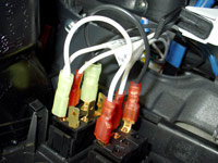
Switches wired up |
Switches installed |
Rheostat relocation.
In the pics above, the switch on the left is for my Footwell lighting mod and the switch on the right is for the this Maplight modification.
Since the factory rheostat switch went in the cutout on the left you may be wondering what happened to it. I relocated it to the area inside the
fuse box located in the driver side lower finish panel. The factory wiring reaches there with no extension needed. I have never used the rheostat
(dash light dimmer switch) on this vehicle or any other vehicle for that matter. I have driven a few road trips thru the night (8 hours of darkness) and
never felt the need to dim the dashboard lights whatsoever. So relocating the switch to an inconvenient area to use was well worth the dash slot that was
freed up.
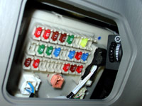
Rheostat relocated |
Running wires to underdash and underseat footwell lighting locations.
At this point we have a white wire and a red wire exiting the drivers side lower dash area. To reiterate, the white wire is the 12V negative source
which started from the ILE circuit, went up to the switch, and back down to the underdash location. The red wire is the 12V positive source and
originated from the dome light circuit located on the back side of the driver side interior relay/junction box.
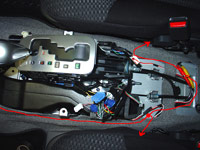
We can now start to run a similar two wire bundle from this driver side underdash location, to the passenger side under dash area, and
the underside of the driver and passenger side front seats. To keep things neat and organized, I like to tape the two wires
together every six inches or so using black electrical tape.
Running wires from the driver side footwell to the passenger side footwell is simple once you have both sides of the center console
side garnish removed. There is plenty of space to pass the wire thru with ease. Leave enough slack at both the driver side and passenger
side footwell areas to make connecting the wires to the light easy and also to enable dropping the lower finish panels down to the floor
in the future.
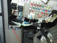
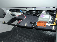
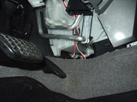
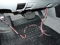
For the rear footwell lights, start by running only one set of wires from the driver side footwell area underneath the carpeting to the
rear of the center console. Once there you can make a splice and run an individual set of wires under the carpeting to each of the
two underseat areas. Again, leave enough slack in the wires to make the connection to the lights and to facilitate moving the seats
within their full range of motion.
Routing wires
one bundle is going to the passenger footwell
the other is going to the rear seating lights |
The red line represents the path taken
under the carpeting to the rear lights |
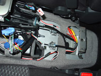
Routing wires to rear footwells
detailed view |
Light Selection.
The switch and wiring are in place now. Let's discuss the Led lights that have been chosen to be used for this project.
At first, I gave much thought to using Flexible Led Strips such as those offered by V-Leds
or Oznium. I decided against them as there is no ideal location
to easily mount a full 12" Led strip where they can be tucked completely out of sight so as to not be seen directly while entering
the vehicle, and not interfere with any surrounding parts.
Next choice was the small form factor Straight 6-Led Modules offered by Oznium.
I ultimately decided against these as the retailer could not give a quote on the approximate lumens that would be produced. My
approximation is in the 20 lumen or less range and therefore at least two modules would be needed per footwell. This would create
additional wiring as well as increase the cost of the project.
Led technology is rapidly advancing and while in communication with one retailer, V-Leds.com,
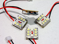
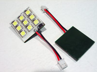
I was made aware of two new products that were not yet listed on their website. One was a 30mm x 30mm ultra thin led circuit board with
self adhesive backing made up of 9 high power surface mount (SMT) Leds. The other was an even smaller and even brighter 6 high power
M-SMT led board sized at 16mm x 16mm x 6mm. The 9-Led board would run at about 1.5 watts and put out approximately 60 lumens.
The 6-Led board would run at 3.0 watts and put out about 120 lumens.
I liked 6-Led board for its very small size and thought these may be ideal for the limited space underneath the rear seats.
The rear seats on the 4th gen Toyota 4Runner really don't have much room underneath them especially on the driver side which has a power
adjustable height feature which I keep set to near the lowest position. Though they do not come with a self adhesive backing,
the 6-Led board's back is flat/smooth and double sided tape can be applied at the time of installation. I also liked the 9-led boards
for their lower power consumption as I was a little worried that the 6-Led boards may generate higher heat levels and that their
120 lumen rating may be a bit bright for this application. So I figured I would order both, try them and return the ones I did not like.
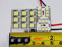
9-led 30mm x 30mm
vs.
6-led 16mm x 16mm |
Testing.
I will detail what I know and have learned about each particular Leds specifications. I feel that it is
important to be informed of and understand this info in order make the right choice for a particular application. You will find that
there are a vast array of 12V Led replacement automotive light bulbs on the market from a wide variety of companies. For example,
for a common incandescent #194 5W bulb there can be literally over 100 different Led replacement choices from various companies,
in various color ranges, running at various power levels, providing vastly different light output, and of course at various price points.
Unfortunately not many retailers make these specs available or provide consistent information on their websites. In fact upon contacting a
few of the companies myself, they simply either don't know, don't care to find out, or don't want to share that type of info. This makes
it hard to comparison shop amongst various competing products. Specs such as "high power", "HID color", "cool white", "super bright", etc.,
really are meaningless without tested numbers to substantiate the claim. As with any product, you have to take the manufacturers or retailers advertised
information with a grain of salt, do your own research beforehand, and follow it up with independent testing.
While I am unable to test the Color Temperature or Luminous Flux ratings due to not having access to that type of testing equipment,
I can confirm the advertised Watts (power) and Amps (current draw). To do this one can use a simple electrical multimeter which can test
the current draw and supply voltages. Multimeters cannot calculate wattage, but you can back into the number by multiplying the
supply voltage by the amperage draw of the electrical load.
Before we discuss how to do this testing, let's discuss why. My goal is to add four high power Led footwell lights to the existing factory dome light circuit.
This is being done, rather than running a new independent circuit, to tap into that particular circuits factory features
(on with remote/key/door operation, off automatically after 30 minutes). No additional relays or fuses will be added to keep the
wiring simple and neat. As long as we don't exceed the factory amperage draw for the dome light circuit, these additional relays and
fuses will not be necessary at all and things will still be completely safe.
I am changing out all the factory incandescent interior courtesy lighting to Leds at the same time as performing the footwell lighting mod.
Since Leds run at a lower power consumption per lumen than incandescent lights do, the savings in watts seen by switching the interior
courtesy lighting over to Leds can be used for the footwell lights in a safe and effective manor.
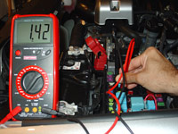
To measure the DC supply voltage of the vehicle's battery, set the meter to volts, and connect the electrical multimeter in
parallel with the battery.
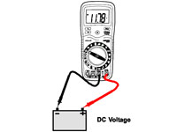
Measuring DC voltage |
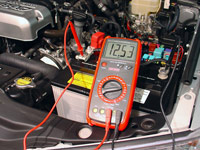
Measuring battery voltage
Vehicle off |
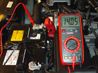
Measuring battery voltage
Vehicle on |
To measure the DC current draw of an electrical load such as an automotive light bulb weather it be incandescent or Led, connect the
multimeter, operating as an ammeter in this case, in series (in-line) with the circuit so that all electrons flowing through the circuit
have to go through the meter.
When a multimeter is placed in ammeter mode, it acts like a simple length of wire, with very little resistance from one test probe to
the other. Consequently, an ammeter will act as a short circuit if placed in parallel (across the terminals of) a substantial source
of voltage such as the vehicle's battery. So be very sure to switch the mode from amps back to volts before connecting it in line
(parallel) with the battery as if you don't you will create a short circuit. Hopefully your meter has a fuse, which will blow in that
situation. If your meter does not have a fuse you will either damage your meter or your vehicle's electrical system.
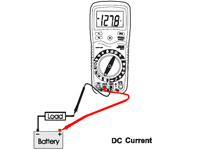
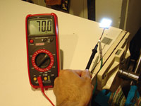
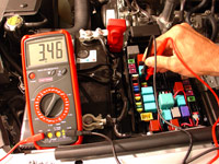
Measuring DC current |
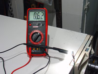
Measuring current draw (amperage)
of the factory dome light
|
Referencing the pics above, let's go thru a basic example checking the wattage of the factory festoon 31mm dome lights (DE3175)
which are known to be rated at 8.0 watts. The wattage of any bulb can be calculated by taking the supply voltage (V=12.5)
multiplying that by the current draw or amperage (A=0.62) which gives a wattage of W=7.8 watts which is right about on target.
The meter being used in these tests is a Craftsman #82170 30 Range, 10 Function Digital Multimeter.
It is accurate to 0.5% when reading DC voltage and 1.5% to 2.0% when reading DC current.
Light Specs.
Footwells:
Led Bulb: V-Leds 6-Led circuit board, 16mmx16mm flat back
Part no.: DIY_6_HP_W_6K-B
Led Type: 6 high power M-SMT
Advertised Kelvin color rating: 6,000k White
Advertised Wattage: 3.0 watts
Recommended forward DC Voltage operating range: 11.5-14.5 volts
Actual metered Amperage: 160.5 milliamps
Actual calculated Wattage at 12.5V (W=V*(MA/1000)): 2.0 watts
Approximate Luminous Flux: 120 Lumens
Comments:
These 6-Led boards were chosen primarily for their ultra small size and high power light output. After fabricating rear under seat
brackets specifically for these lights and making the final wire connections, it became immediately apparent that these lights
were too bright for this particular application. The high light output would reflect off my Floor Liners
which are made of a rubberized thermo-plastic material, producing glare which would definitely annoy rear seat passengers.
I decided not to use these lights, even for use up front. I tried them out as dome lights and they met my needs perfectly for that
application. More details on that can be found at my Interior Led Lighting page.
6-Led board |
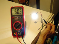
6-Led board amperage
160.5 milliamps |
Next try was the 9-Led boards.
Footwells:
Led Bulb: V-Leds 9-Led circuit board, 30mmx30mm flat back
Part no.: CMYT-336-9LED This has been discontinued, I recommend STRIP_RL_INT_12-C as a replacement
Led Type: 9 high power SMT
Advertised Kelvin color rating: 6,000k White
Advertised Wattage: 1.5 watts
Recommended forward DC Voltage operating range: 11.5-14.5 volts
Actual metered Amperage: 70 milliamps
Actual calculated Wattage at 12.5V (W=V*(MA/1000)): 0.9 watts
Approximate Luminous Flux: 60 Lumens
Comments:
These 9-Led boards run at half the light output of the 6-Led boards. At 30mm x 30mm they are still small enough to be inconspicuously
mounted under the rear seats without interfering with passengers feet or objects set on the floor. 1.5 watts and 60 lumens each is still
considered high power. The hope was that this light choice would give off a less harsh output in this small confined area and have
no hot spots. They met this expectation.
They come with a self adhesive backing and are very thin. Thinness is a concern especially for the front passenger footwell as there is a
plastic finish panel under the dash in that location and I was worried about having the light itself being hit by passengers legs or
packages.
9-Led board |
9-Led board amperage
70 milliamps |
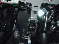
Fabrication of brackets needed to mount the Led lights.
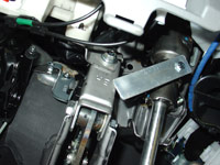
While the underside of the passenger side dash area does have a smooth flat location to mount circuit board type Leds without the use of
a bracket, the other three footwell areas do not. We would need to fabricate some sort of bracket to mount the Leds to.
The driver side bracket is the easiest to make. If you look under the driver side dashboard, on the steering column shaft, there is a
factory welded on tab which is pre-threaded and unused. I am not sure why it is there but is makes for a great place to mount a
sturdy bracket made of 1" x 1/4" aluminum flat stock. You can pick up a piece of aluminum 1" wide by 48" long at your local Home Depot,
Lowes, or similar hardware type store. Using a hack saw cut a piece off about 4" long. Drill a 1/4" hole in one end. Be sure to file
and round off all sides and cut edges including the drilled hole. A 20mm long, 1.0 pitch (fine threaded) M6 bolt will fit into the
factory threaded tab on the steering column perfectly. You will need about 5 washers to be used as a spacer between the factory tab
and the bracket so the bolt won't bottom out. This spacer also puts the bracket in a better position as well.
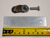
Driver side
light bracket, bolt and washers |
Driver side
under dash light bracket
installed |
Now for the rear seat brackets.
As I mentioned earlier, the 6-Led boards turned out to be too bright for this application, and ultimately were not used.
However, this type of bracket may prove to be useful information for someone else’s mod. Below is the method that I used to create each
of the two bracket types.
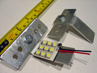
First I will show you how I made the brackets for the 6-Led boards. Starting out with a 48" piece of 3/4" angle aluminum, which
again can be purchased at your local Home Depot, Lowes, or similar hardware type store. Use a hack saw to cut off a piece about 3.5" long
for each of the two brackets we will need. Drill four 1/4" holes thru each bracket, as shown in the pic below. Be sure to file and round
off all sides and cut edges including the drilled holes. If you look underneath the seats you will see two thin metal bars
running from back to front. This is where we will mount the brackets using two cable ties per bracket.
If you mounted the led to the 90 degree bracket without further modification the light would shine primarily straight back to the
rear of the vehicle. The the material on the backside of the seat hangs down at a slightly lower level than where the light will
be mounted and will interfere with the light creating a shadow, therefore I needed to bend the bracket into a 45 degree angle
which will project the light downward and backward.
To connect the 6-led board to the bracket I used double sided thermal transfer adhesive tape made for computer chipsets and RAM heatsinks.
The tape is very thin and holds quite well. It can be found on Ebay for a very low cost. It comes shipped as 1" wide strips by 6" in length
and can be cut to any size you need. This method of mounting the Led board to the aluminum bracket allows the heat to pass thru to the
aluminum which can then act as a heat sink for these high power 3.0 watt Leds.
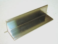
3/4" angle aluminum
going to be used to make
the 6-led board bracket |
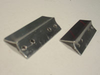
Under seat bracket for 6-led board
bent to a 45 degree angle |
Bracket and led installed - driver side |
Bracket and led installed - passenger side |
While I will get into explaining the process of making the final wire connections a little later, I am going to jump ahead here and
show you a pic of the light output from the 6-Led boards vs. the lower power 9-Led boards in the rear seating footwell area.
The 6-Led boards were simply too bright for my liking to continue with the installation of these boards up front.
I initially chose the 6-Led boards for their combined ultra small size and high power light output. I felt the small sized light was well
suited for the small space under the rear seats. Additionally the high power would allow the light to be mounted further frontwards so as
to not interfere with the passengers feet while at the same time having enough output to completely light up the footwells.
But, the rubberized thermo-plastic material of my floor liners has just enough reflectiveness to make such a high power led too annoying.
Sure the 120 lumens looked great entering and exiting the vehicle. But part of the reason I have the three way switch installed is so
that I can turn the footwells on while driving in complete darkness and perhaps leave them on as desired for extended periods of time.
What I didn't want was super bright light reflecting up into the front or rear passengers night time constricted pupils.
I was able to repurpose these two 6-Led boards and use them as my dome and cargo lights. They are well suited for that application.
9-led board light output on the driver side
6-led board light output on the passenger side
1 second exposure time |
On to the process of making brackets for the 9-Led boards. These boards are 30mm square which is 1.18". The 1" wide aluminum flat stock
used to make the driver side bracket is nearly perfect for these, and no change to that bracket is needed. The 9-Led boards will extend
slightly past the edges of the 1" aluminum but that poses no issues at all.
To make the rear seat brackets for the 9-Led boards, use a hack saw to cut off four pieces of the 1" wide flat aluminum stock about
3.5" long, as two pieces are needed to make each bracket. Drill five 1/4" holes thru two of the pieces as shown in the pic below
and one in the other two. Be sure to file and round off all sides and cut edges including the drilled holes. Connect the brackets
that have five holes to the brackets with one hole, forming a t-shaped bracket. Use an M6 or 1/4" bolt and nut combination to make the
connection and cut off the excess bolt length with a hack saw to keep things flush. Put the bracket in a vise and bend the undrilled
portion into a 45 degree angle, this will better position the light so it fills the footwell without any shadows. Looking underneath the
seats you will see two thin metal bars running from back to front. This is where we will mount the brackets using two cable ties per
bracket.
The 9-led boards come with double sided tape pre-installed so after cleaning the bracket with a little alcohol they will attach securely.
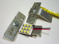
Under seat bracket for 9-led board |
Under seat bracket for 9-led board |
Making the final wiring connections.
At this point we have run the footwell circuit wiring, installed and wired the switch, fabricated our brackets and mounted them. We are
now ready to connect the footwell circuit wiring to the footwell led boards and mount the boards onto their bracketing.
The drivers side front seat footwell is where all our wires started out. In this pic the two wire bundle on the left is the
source wiring, again the white wire is the negative from the switch and the red is the positive from the dome light circuit.
The wire bundles on the right are the wires that go to the passenger front seat, and to the rear seats.
These wires are all 18 gauge.
Wires under the driver side dash panel |
To connect these wires to the 20 gauge Led wires, I will do that in 2 steps.
Step 1, strip all the wires back exposing approximately 3/8" of the copper stranded wire.
Twist the three red wires together, and do the same for the white wires. Cut off a piece of red and white 18 gauge wire, each a few inches long.
Strip back the ends of these as well. Slide onto each of these cut pieces of wire a 1.25" long piece of
1/4" diameter heat shrink tubing.
Insert the three red wires into one end of a
12-10 gauge parallel non-insulated crimp connector,
then insert the single red wire in the other end. Crimp the connector. Do the same for the white wires. Slide the heat shrink tubing
into place over the crimped connectors, and heat using a lighter.
Step 2, take the other end of each one of the single piece of 18 gauge wires and connect it to the 20 gauge Led wire using a
22-18 gauge parallel non-insulated crimp connector.
Be sure to fit a piece of 1/8" diameter heat shrink tubing
into place first. Again, make the crimp connection and heat the tubing to make a professional and secure connection.
Connect the wires together
using crimp type parallel connectors |
Close up view |
Finished connection |
At this point we can clean the bracket with a little alcohol, peel the backing off the self adhesive tape pad, and affix the led board
to the bracket. Secure the wires up behind the dash trim panel using wire ties and/or tape. Repeat this procedure for the other
three led locations.
Driver side
light mounted to bracket |
Front seat pics, led boards mounted and tested.
Driver side
light mounted to bracket |
Driver side
light tested |
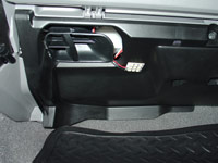
Passenger side
light mounted to under dash trim panel |
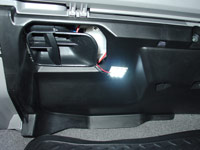
Passenger side
light tested |
Rear seat pics, led boards mounted and tested.
Rear driver side
light mounted to bracket |
Rear driver side
light tested |
Rear passenger side
light mounted to bracket |
Rear passenger side
light tested |
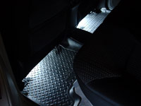
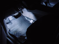
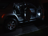
Footwell light output pics.
All pics in this section have a consistent exposure time of 1 second.
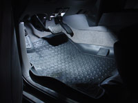
Driver side footwell lighting |
Driver side footwell lighting |
Passenger side footwell lighting |
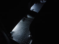
Rear footwell lighting |
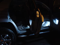
All lights on (doors, domes, maps)
Without Footwells |
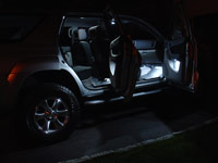
All lights on (doors, domes, maps)
With Footwells |
Animated comparison |
 |
Power consumption.
In the Testing section above, my concern was that since we are adding four high power Led footwell lights to the existing factory
dome light circuit we would need to ensure that we don't exceed the factory amperage draw for that circuit.
The 9-Led board amperage was measured 70 milliamps or 0.9 watts each.
9-Led board amperage
70 milliamps |
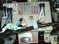
After installation, I measured the dome light circuit draw with only the four footwells on. This can be done easily by removing the
dome light circuit's 10 amp fuse located in the engine compartment fuse box, and connecting the meters probes there instead.
Remember that the vehicle battery voltage varies between 12 to 14 volts, that combined with the fact that the Led bulbs amperage draw
will vary with the supply voltage and temperature changes, results in a slightly higher than expected (70ma * 4 = 280ma expectation)
350 milliamp or 4.4 watt total draw from the footwell lights.
If you have read my Led Interior lighting page, you will know that I reduced the dome light circuits
power consumption by 25 watts by switching out the factory incandescent lights for Led lights. Therefore, the addition of 4.4 watts for
the footwell lighting is well within spec.
Before - Incandescent
domes, maps, doors, vanities
3,460 ma or 43.3 watts |
After - Leds
domes, maps, doors, vanities
1,420 ma or 17.8 watts |
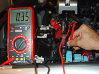
Led footwells only
350 ma or 4.4 watts |
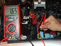
Led domes, maps, doors, vanities, footwells
1,650 ma or 20.6 watts |
Special Offer:
I have purchased all the above Led lights from one source, V-Leds.com.
The decision to go with them for all the lights was based on much advance research into their product line, communication
with them via email as well as customer feedback found on a wide variety of online automotive forums. I have had nothing but
excellent customer service from this company.
V-Leds Coupon offer:
Join the V-Leds Newsletter and get 15% off your next order!
One Year Update:
I have had various V-Leds bulbs installed for over one year now and I have had absolutely no issues or problems at all.
I continue to return to them for all my automotive LED and HID bulb needs.
|
|