|
Main Menu
|
|
|
|
My 2007 4Runner
|
|
|
|
|
|
|
|
|
|
|
|
|
*New*
|
|
|
|
|
|
|
|
|
|
|
|
|
|
|
|
|
|
|
|
*New*
|
|
*New*
|
|
|
|
|
|
|
|
|
|
|
|
|
|
|
|
|
|
|
|
|
|
|
|
|
|
|
|
|
|
*New*
|
|
|
|
|
|
|
|
|
|
|
|
|
|
|
|
|
|
|
|
|
|
|
|
|
|
|
|
|
|
|
|
|
|
|
*New*
|
|
*New*
|
|
*New*
|
|
|
|
|
|
|
|
*New*
|
|
*New*
|
|
*New*
|
|
*New*
|
|
|
4Runner History
|
|
|
|
Other
|
|
|
|
|
Concept:
This modification will change the operation of the optional factory Daytime Running Lights (DRLs) on the 4th generation Toyota 4Runner so that using a switch they can:
ON - remain on at all times
OFF - remain off at all times
AUTO - operate as per OEM (on when headlights are off, off when headlight are on)
Daytime Running Lights (DRL) was an option on my 2007 4Runner (option code RL) and was priced at $40 retail and $32 invoice.
This system is designed to automatically activate the turn signal lights during the daytime to keep the car highly visible to other vehicles.
This system is controlled by the Body ECU and the Daytime Running Light & Turn Signal Flasher Relay.
It makes use of the turn signal lights as daytime running lights.
For this reason, when the turn signal lights are operated, the daytime running lights function is interrupted momentarily, which however,
will be brought back into operation as soon as the interposed operation is over.
The factory DRL system is enabled when the conditions given below are met.
A) Ignition switch ON condition
B) Turn signal light switch OFF condition
C) Hazard light switch OFF condition
D) Light control switch OFF condition
E) Parking brake switch OFF condition (Parking brake out of operating condition)**
** This system does not become active when the parking brake switch is ON. However, once the OFF signal of the parking brake switch is input into the body ECU,
this system will become active thereafter, regardless of whether the parking brake switch is ON or OFF.
This modification adds a double throw switch so that the operation of the DRLs can be changed as desired.
An always off mode will be useful in certain situations when you want to go stealth and have all exterior lighting off.
An always on mode will be useful to keep the DRLs on with the headlights, when normally they would automatically switch off.
What needs to be accomplished:
The Body ECU communicates with the Daytime Running Light & Turn Signal Flasher Relay.
It sends a ground signal to this relay when the DRLs are to be activated.
This mod uses a three position switch that will either override, interupt, or allow for OEM operation of this DRL activation signal.
We will tap into this signal at the Daytime Running Light & Turn Signal Flasher Relay which is located on the back side of the driver side interior relay/junction box.
Procedure:
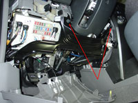
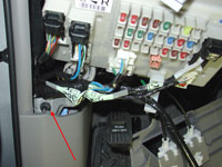
Remove driver side lower finish panel for access to driver side interior relay/junction box.
Start out by disassembling the lower dash area as we need access to the driver side interior relay/junction box. To access this area,
first remove the two 10mm bolts holding the lower finish panel on. Pull the panel straight out to disengage 4 plastic clips still holding it on.
The trim ring around the key hole will just pop out on it's own as you are doing this. Remove the wire harnesses attached to each of the switches
located on the back side of this panel. Also on the back right side of this lower finish panel is the room temperature sensor harness (cooler thermistor),
detach this from the panel as well. You may leave the fuel door release and the hood release handles attached to the panel. The panel can be lowered
to the floor now.
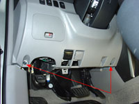
Remove driver side
lower finish panel |
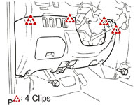
Pull to release 4 clips |
Remove lower bracket:
Remove two 10mm bolts holding the metal bracket around the bottom of the steering column. Disengage the 2 claws and remove the instrument panel lower
left hand bracket. Set bracket aside.
Remove instrument panel
lower bracket |
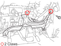
Disengage 2 claws |
Lower down the driver side interior relay/junction box:
Remove wire clip and wire connector under steering column.
Remove three bolts holding driver side interior relay/junction box in place.
Remove bolt & bracket.
Pull down driver side interior relay/junction box to access back side.
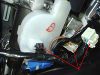
Remove wire clip
and wire connector under steering column |
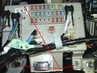
Remove three bolts |
Remove bolt & bracket |
Remove instrument cluster finish panel.
Pull firmly straight out to release seven clips.
Remove Rheostat (dash light dimmer) by unclipping wire harness on the back, depressing two tabs on this switch (top and bottom) and pulling the switch
out the front of this panel. Set panel aside.
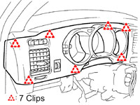
Remove instrument cluster
finish panel
Pull to release 7 clips |
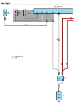
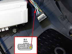
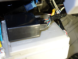
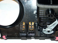
Tap into the DRL circuit.
Locate D2 Connector on Daytime Running Light & Turn Signal Flasher Relay which is mounted on the back of the driver side interior relay/junction box.
Identify Pin #12, light green with red stripe wire. This is the wire that the body ECU uses to send the ground signal to the Daytime Running Light & Turn Signal Flasher Relay.
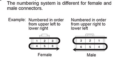
Pin Numbering System |
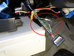
Cut this wire in half, one inch from the connector. Connect a 22" length of 18awg (American wire gauge) wire to each of the cut sides and run this wire from here up to where you will mount the dash switch.
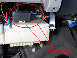
DRL Relay
Connector D2 |
Pin #12
Light green with red stripe wire |
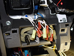
Cut #12
Light green with red stripe wire |
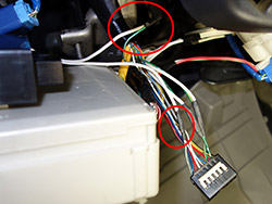
Splices completed at the
Body ECU to DRL ground wire |
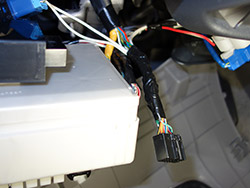
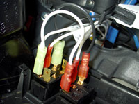
Wire bundle
taped up |
Wire bundle
reconnected |
Switch information.
A SPDT (single pole double throw) switch with on-off-on functionality will be used to activate the three modes of this mod.
Up Position: ON - DRLs remain on at all times, even when the headlights are on (switch prongs 2-1 connected together).
Center Position: OFF - DRLs remain off at all times (switch prong 2 not connected to anything)
Down Position: AUTO - operate as per OEM (on when headlights are off, off when headlight are on) (switch prongs 2-3 connected together).
Cole Hersee Part# 58027-03
Switch Type: Rocker Switch
Circuitry: Single Pole Double Throw (SPDT)
Terminals: 3 standard male brass blades, 0.25" wide x 0.50" long (6.35mm x 12.70mm).
Up Position: On (2-1).
Center Position: Off.
Down Position: On (2-3).
Electrical Rating: 25 amps at 12 VDC.
Sealing: Weather resistant, gasket seal in housing.
Contacts: silver.
Illuminated: No.
Housing: Black plastic bezel and actuator.
Mounting Panel snap-in.
Panel Thickness: fits panels 0.093" to .187" (2.37mm x 4.76mm) thick.
Mounting Hole Dim. Inch 1.45" x .830" (36.83mm x 21.08mm).
Bezel Size: 0.964" x 1.69" (24.52mm x 43.16mm).
Actuator: inches 1.19" x .660" (30.3mm x 16.9mm).
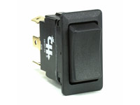
Cole Hersee SPDT 58027-03 |
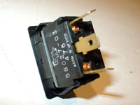
Cole Hersee SPDT 58027-03 |
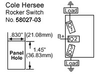
SPDT Switch Schematic |
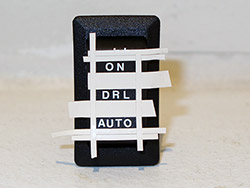
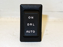
Switch Labeling.
The Cole Hersee 58027-03 switch that I chose to use has a blank front which is perfect for a custom labeling job.
I purchased a set of Woodland Scenics Dry Transfer Decals MG721 White Gothic Letters. To protect it I went with Testors Dullcote 3oz Spray Can TES1260.
To layout the lettering as straight and centered as possible, I used some leftover 25 year old pinstriping I had laying around from my 1984 Oldsmobile Cutlass Calais project.
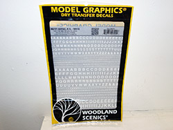
Woodland Scenics
Dry Transfer Decals
MG721 White Gothic Letters |
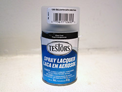
Testors Dullcote
3oz Spray Can
TES1260 |
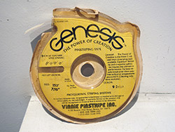
Pinstriping |
Laying out the
Dry Transfer Labeling |
Lettering completed |
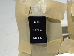
Spraying
the matte finish
protective topcoat |
Switch installed |
Switch Mounting.
The Cole Hersee 58027-03 switch that I chose to use fits perfectly in the instrument cluster finish panel (upper dash) cutouts with
no modification or trimming necessary to either the switch or the panel. Though the switch does not snap lock into place due to the
thickness of the panel, the fit on the sides is more than tight enough to hold it in place.
Switches mounted in dash |
A look from the back |
Switch wiring.
At this point we have already ran two wires from the cut #12 wire at the DRL relay to the switch location.
The side of the cut wire coming from the Body ECU should be connected to the bottom switch prong.
The side of the cut wire coming from the D2 Connector on Daytime Running Light & Turn Signal Flasher Relay should be connected to the middle switch prong.
To make the connections to the switch prongs I use red 3M Nylon Fully Insulated Female Disconnects with insulation grip interlock barrels.
Red is typically used for 22-18awg wire. These disconnects fit quite tightly onto the switch prongs which is why I prefer this type that has an insulation grip interlock barrel.
These type of connectors require a double crimping method, the first crimp to secure the copper wire itself, the second crimp is on the wire insulation further securing the wire.
This helps to hold the wire securely in place when you need to pull on the disconnect to remove it from the switch, which can be difficult to remove due to the tightness.
A dab of dielectric grease on the switch prong will assist in future removal efforts as well.
Lastly, the top switch prong should be connected directly to ground. Using a 5" piece of 18awg wire, crimp a ring terminal on one end and a quick disconnect on the other.
Screw the ring terminal end to the screw that holds the driver side air vent to the dash reinforcement bar, this provides a constant ground source.
Connect the other end to the upper switch prong.
Wires for DRL Mod,
Footwell Lights
and Maplight Mods |
Switches wired up |
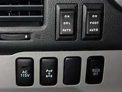
Switches installed |
Rheostat relocation.
In the pics above, the switch on the left is the one for the DRL mod and the switch on the right controls both the Footwell lighting
and Maplight mod.
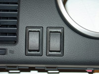
Since the factory rheostat switch went in the cutout on the left you may be wondering what happened to it. I relocated it to the area inside the
fuse box located in the driver side lower finish panel. The factory wiring reaches there with no extension needed. I have never used the rheostat
(dash light dimmer switch) on this vehicle or any other vehicle for that matter. I have driven a few road trips thru the night (8 hours of darkness) and
never felt the need to dim the dashboard lights whatsoever. So relocating the switch to an inconvenient area to use was well worth the dash slot that was freed up.
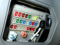
Rheostat relocated |
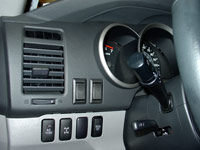
Pics.
In the pic below, you can see what it looks like to thave the DRLs remain on with the headlamps.
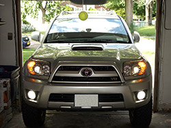
DRLs on with Headlights |
|
|